Building a Video Processing Hardware Acceleration Simulation Platform Quickly with Simulink
How to build hardware accelerator using Simulink
Preface
In this tutorial, we’ll use Simulink to quickly build a hardware acceleration platform for image/video processing, using the simple RGB2GRAY algorithm as an example. The main toolboxes we’ll be using are HDL Coder and Vision HDL Toolbox, and later we’ll add related Hardware Support Packages. You can explore the functions supported by these toolboxes in Simulink’s Library Browser or on the MathWorks website.
First, create a new Simulink model and configure it as described in the previous tutorial.
Then, double-click on the blank workspace and add the following modules:
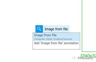
- Image From File
- Frame To Pixels
- Pixels To Frame
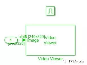
- Video Viewer
- Enabled Subsystem
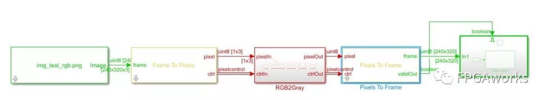
Place the Video Viewer inside the Enabled Subsystem, as shown in the figure below.
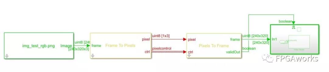
Then, connect all the modules as shown. Each module has two input signals: pixel and ctrl. The pixel signal represents the pixel value. The ctrl signal indicates the start and end of rows and columns, as well as the valid signal. If you’re not familiar with this, refer to MathWorks’ documentation on the video interface control bus:
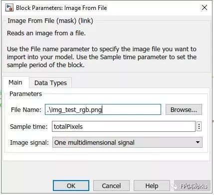
Next, configure the Image From File block. Double-click it and set the File Name and Sample time, as shown below.
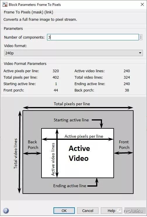
Then, configure the Frame To Pixels and Pixels To Frame blocks. Since our image format is RGB 240p, select Video Format = 240p, and set Number of components = 3 (for RGB’s three channels). For Pixels To Frame, use the same settings. If you’re not familiar with video formats, read the Video format section in MATLAB’s Frame To Pixels documentation
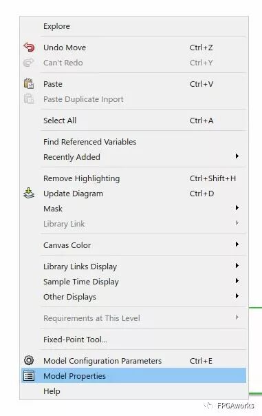
Next, set the simulation parameters. Right-click on a blank area of the model and select Model Properties.
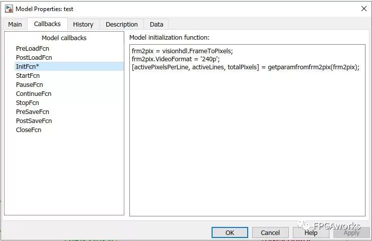
In the Callbacks -> InitFcn (Initialization Function) section, enter the following code so that the model can automatically retrieve image width, height, and other parameters when the video format changes.
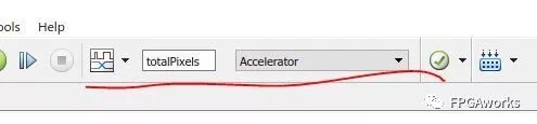
After that, in the model configuration bar, set the Simulation time to totalPixels (configured in the previous step), and set the simulation mode to Accelerator.
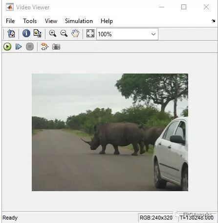
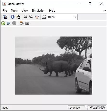
At this point, we can test the simulation pipeline. Save the model and press Ctrl+D to check its integrity. If there are no errors, click the Run button to start the simulation. If everything works correctly, you should see the following output image.
Since the video pipeline is now functioning, we can begin adding our custom RGB2GRAY module. Those familiar with digital image processing know that the RGB-to-gray conversion formula is:
\[GREY=0.299×R+0.587×G+0.114×B\]We build the conversion module as follows:
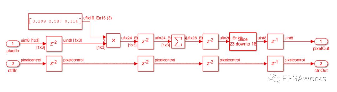
The Delay block acts as a register. The RGB signals enter through pixelIn, are multiplied by their corresponding constants via Multiplier blocks, summed using the Sum of Elements block, and finally converted to uint8 (by truncating to 8 bits before the decimal point) using the Data Type Conversion block. The Control Bus also requires corresponding delays to maintain timing alignment. (Why two register delays are used and how multipliers can be replaced will be discussed in a later section.) Encapsulate this part of the model into a subsystem (select the desired blocks -> right-click -> Create Subsystem from Selection). At this point, the algorithm construction is complete, as shown below. Since the grayscale image has only one channel, don’t forget to set the Number of components = 1 in the Pixels To Frame block.
Run the simulation again — if successful, the Video Viewer will display the grayscale image, indicating our conversion algorithm works correctly.
Attentive readers may notice that all the modules used to implement the RGB2GRAY algorithm come from the HDL Coder Toolbox. You can find more examples and supported functions on the MathWorks website.
MathWorks provides a corresponding hardware framework that allows users to quickly build algorithm verification and testing platforms — mainly from the Xilinx Zynq Support from Computer Vision Toolbox. In the model shown earlier, the green and yellow blocks cannot be synthesized into hardware code directly. However, when adapted to the corresponding Zynq framework, users can easily implement their algorithms in hardware by following the same pixel and ctrl interfaces.
I have also added the software-side verification in my GitHub repository, including PSNR computation between the hardware and software results. You’re welcome to download and test it on your own system. If you have any questions or suggestions, feel free to contact me.
Coming Next
In the next tutorial, we’ll explore: Which modules can be converted into HDL code, How to deploy the model to hardware, And some key implementation techniques.
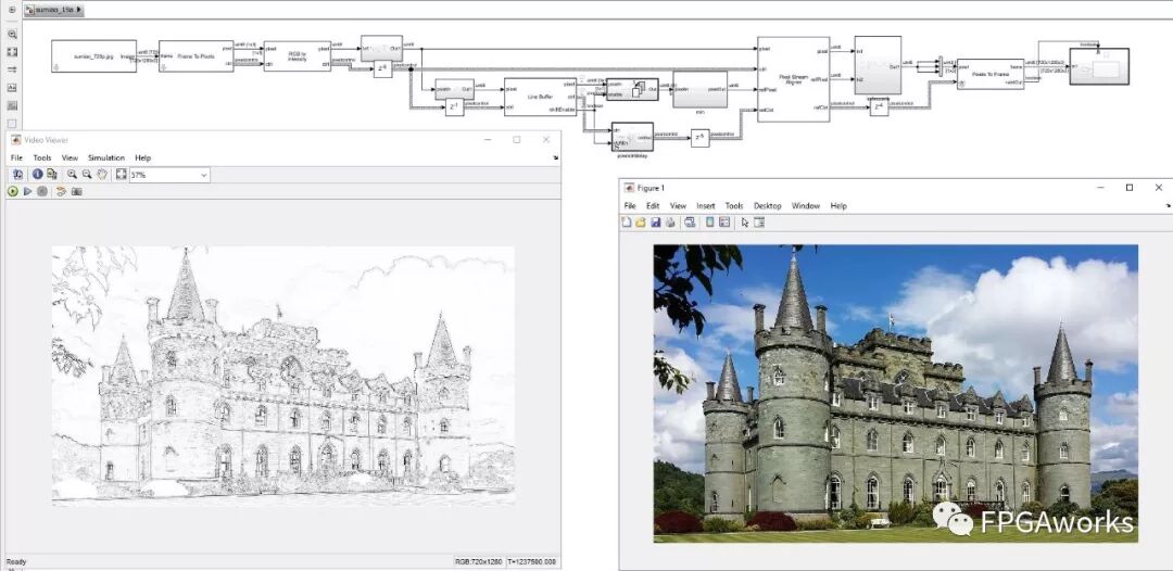
Specifically, we’ll generate the HDL code for the above model and verify it on a ZedBoard + FMC-HDMI-CAM setup. We’ll also learn how to use Line Buffers, how to generate patches, and how to implement a photo-to-sketch transformation (sample image from wyfunique’s GitHub; please contact me if any copyright issues arise).
The resulting output is shown below (right: input image; left: hardware-implemented output).