Deploying Video Algorithms to Hardware Based on Simulink
How to validate hardware accelerator framework using Simulink
In the previous section, we completed the verification platform setup and algorithm validation in Simulink. Now, we’ll load the implemented RGB2GRAY module into MATLAB’s acceleration platform, ultimately deploying the algorithm to the FPGA. In this section, we’ll use the Computer Vision Toolbox Support Package for Xilinx Zynq-Based Hardware.
First, open the Simulink Start Page click the corresponding package, and select RGB HDL Pixel-Streaming Algorithm with Zynq.
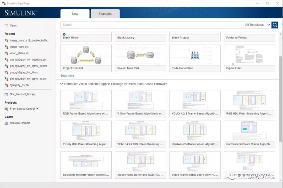
Since our algorithm is designed for RGB, we select the RGB template. For FPGA processing, images are handled pixel by pixel, so we choose the Pixel-Streaming template.
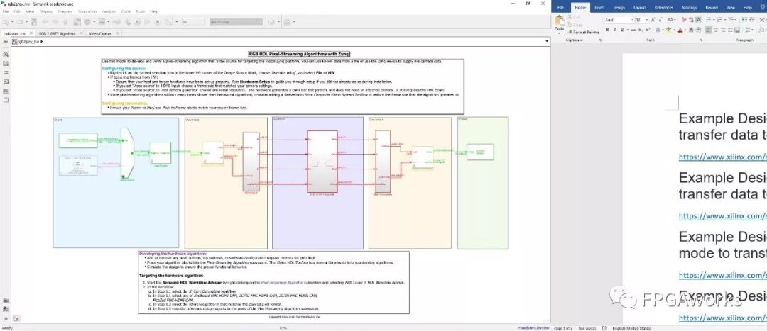
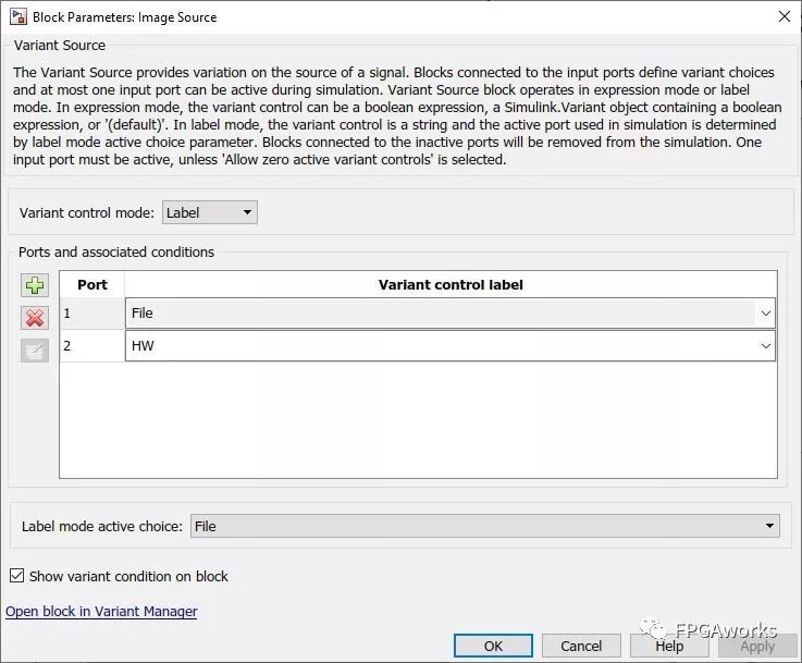
We can see the model is divided into five parts: Source, Conversion, Algorithm, Conversion, and Display. As a verification platform, users can choose to use a video file from the PC or a camera/HDMI source connected to the FPGA. Double-click Image Source to select your video source.
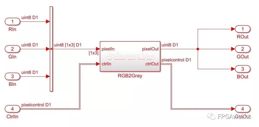
Because the input format is fixed (1080p60), the Image Resize block can resize the image as needed. The RGB Selector block separates the three channels. In the Algorithm section, we insert the previously verified algorithm module. The constant blocks are controlled via the AXI4-Lite bus; since our RGB2GRAY module is not configurable, we can remove them.
Because our module’s input and output are pixel-based, we must recombine the three RGB channels and connect the pixelOut signal to the output RGB channels to produce the grayscale output.
Save, press Ctrl+D, and run the model. We can observe that the RGB2GRAY module runs successfully.
Next: Generate Hardware Code with HDL Coder
First, in MATLAB’s command line, enter a command like the following so HDL Coder can locate the Vivado path:
1
hdlsetuptoolpath('ToolName','Xilinx Vivado','ToolPath','C:\Xilinx\Vivado\2018.2\bin')
It’s recommended to use:
1
visionhdlsetup('NAME_OF_THE_SIMULINK_MODEL')
This applies the recommended settings from the Vision HDL Toolbox. (Note: some warnings may appear during hardware code generation, but they can be safely ignored, this will be explained later.) Right-click the algorithm module -> HDL Code -> HDL Workflow Advisor.
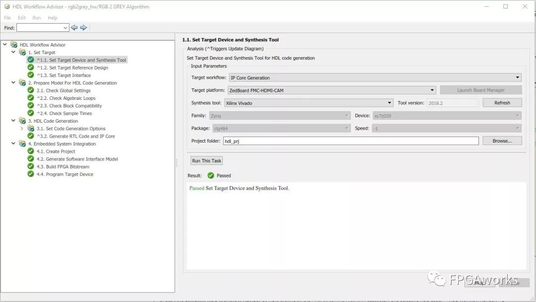
Step 1.1
Configure it as shown below. Since I’m using ZedBoard + Video Daughter Card and Vivado 18.2, my settings are as follows.
Step 1.2
Here we can see the Reference Design used for RGB mode (we’ll discuss reference designs later; they can be customized for various applications). Use the default configuration for now - no changes needed.
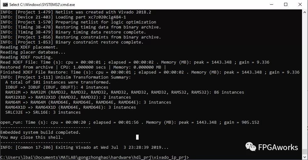
Right-click 4.3, select Run to This Task. If a “balance” warning appears in Step 2, simply ignore it. Step 4.3 will open a new CMD window showing Vivado synthesis and implementation progress - wait patiently until it completes.
Meanwhile, several new windows will pop up: Vision Zynq Targeted Hardware Interface Model and Vision Zynq Targeted Software Interface Model.
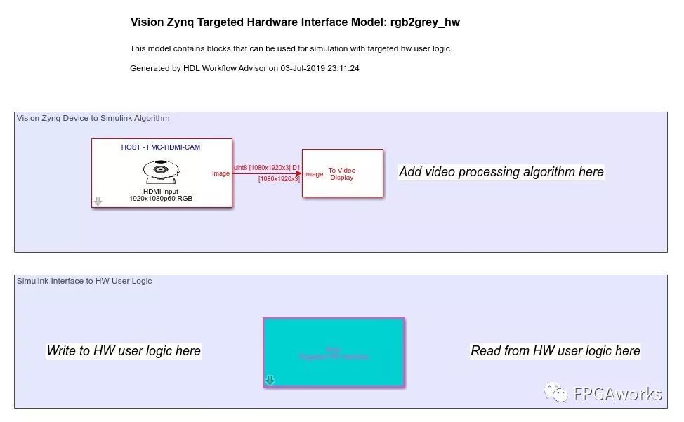
Using these, we can create an emulation environment. The first runs purely in hardware, while the second supports hardware-software co-simulation (the ARM processor configures hardware IP registers via AXI-Lite; our module lacks such configuration, so we’ll cover this later). Simulink also provides a capture module, allowing visualization without connecting a physical display.
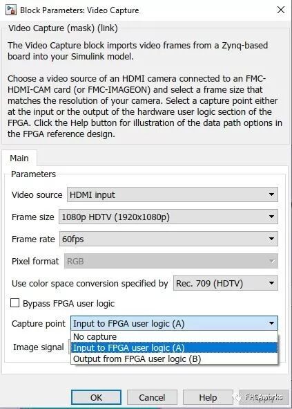
In the Hardware Interface Model, add a To Video Display block and connect it to the camera input. Double-click the camera block to select Image Signal. Choosing (A) shows the image entering the board, as in the figure below. If everything works correctly, the (B) output will display the grayscale version.

When 4.3 finishes, run 4.4 to write the bitfile into the ZedBoard. Now we can perform emulation. Make sure the Hardware Interface Model mode is set to External, and run it - you should see the image below, confirming that the algorithm was successfully deployed on hardware. The “External” mode means Simulink streams video input to the ZedBoard, receives the output, and displays it directly in Simulink.

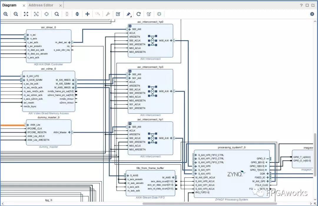
Finally, let’s examine the generated Block Design. Two DMAs transfer data via HP0 and HP3. One is Xilinx’s AXI DMA, and the other is ADI’s DMA Controller—the latter is the active DMA. The former connects to a FIFO on both ends, but the FIFO isn’t connected to other modules.
Additional Notes
Other supported FPGA boards include ZC702 and ZC706. For first-time users, please complete initialization according to Installation and Setup - Computer Vision Toolbox Support Package for Xilinx Zynq-Based Hardware
More details can be found in the references below.
The entire project is stored in Hardware model repository
References
[1] Create Model Using Simulink Templates
[2] Computer Vision Toolbox Support Package for Xilinx Zynq-Based Hardware