MATLAB HDL Coder Development Environment Setup
How to setup environment for Simulink-based Hardware Development
MATLAB HDL Coder + Simulink is much more user-friendly for vision developers compared to Vivado HLS. However, MathWorks’ examples are, as always, somewhat disorganized. Therefore, I plan to regularly update a series of tutorials based on HDL Coder, hoping they will be helpful to everyone.
Required Software Versions
MATLAB 2018b + HDL-related toolboxes. When using MathWorks’ HDL toolbox series, we recommend working within the Simulink environment. Simulink provides better control over timing, and by using the modules provided in the toolbox, it helps avoid generating non-synthesizable code. MATLAB code, on the other hand, is more suitable for implementing combinational logic, such as statevmachines.
Step 1: Create a New Simulink Model
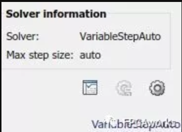
First, create a new Simulink model. Then, click VariableStepAuto in the bottom-right corner (as shown in the image below), and click the gear icon to open the Configuration Parameters menu.
Step 2: Configure Fixed-Point Discrete Environment
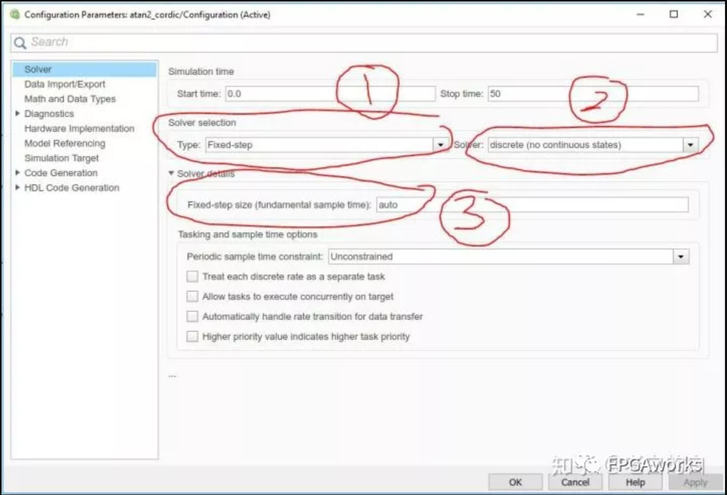
As shown in the figure below, set circles 1 and 2 to configure the Simulink environment for fixed-point discrete mode. Circle 3 usually doesn’t need to be changed to 1, but if you encounter an error saying your solver is not set to 1, changing this “auto” value to 1 might save your model.
Step 3: Configure Hardware Implementation
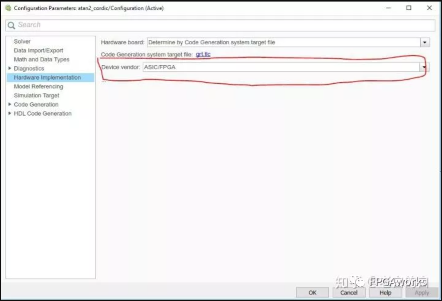
The default Hardware Implementation option targets an x86-64 system. We need to change it to ASIC/FPGA.
At this point, our Simulink environment setup is complete, and we can start building our model. In the next tutorial, I’ll use RGB-to-Gray color conversion as an example to demonstrate how to quickly build and verify an image/video processing pipeline.